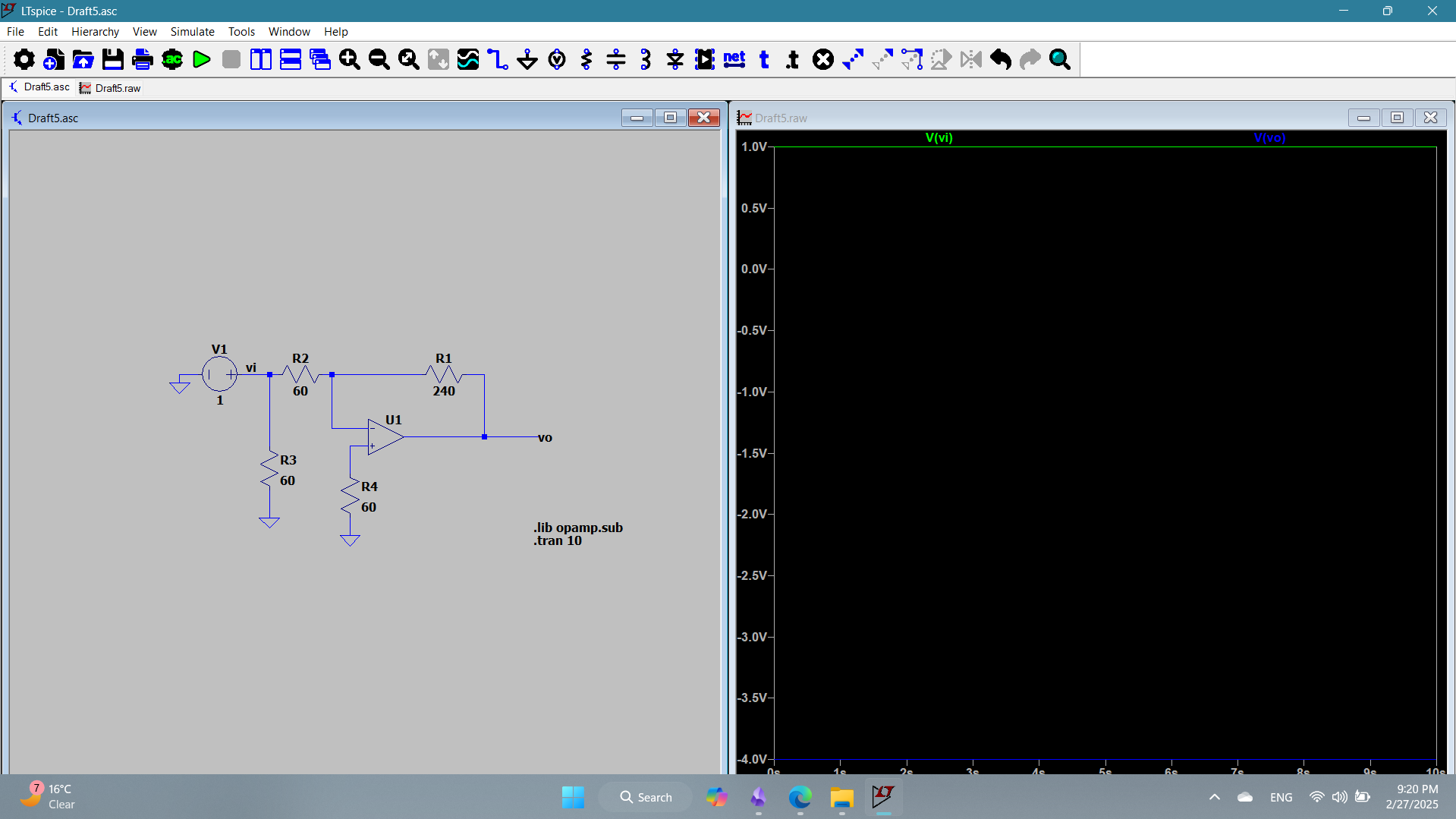
1a
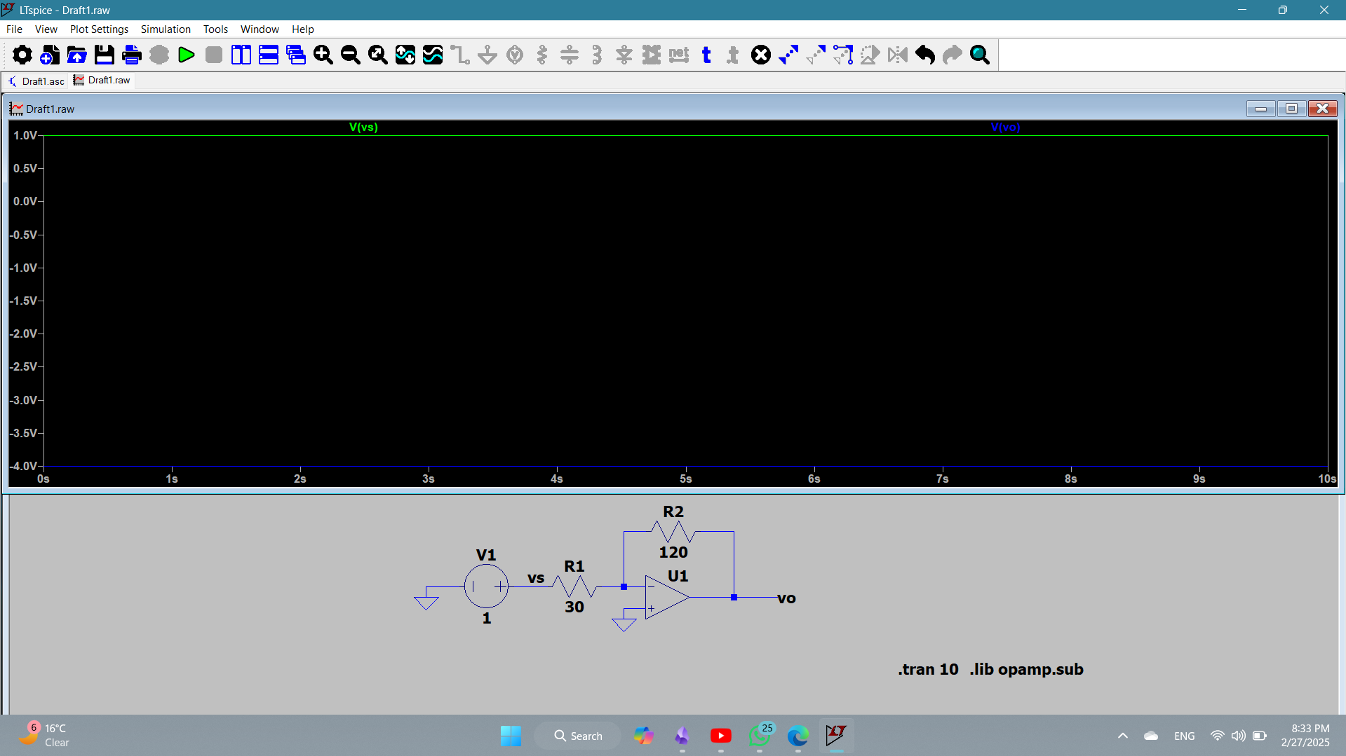
The circuit represents an inverted amplifier configuration with a gain of -4. The input voltage is 1V (green), and output voltage is -4v (blue).
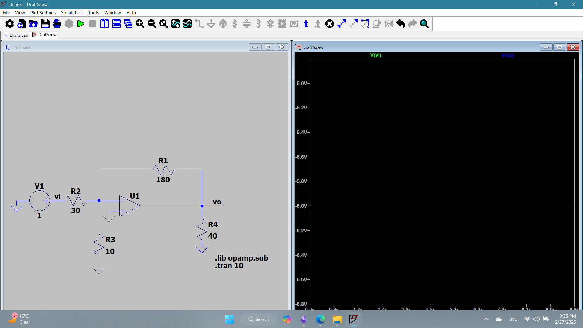
1b
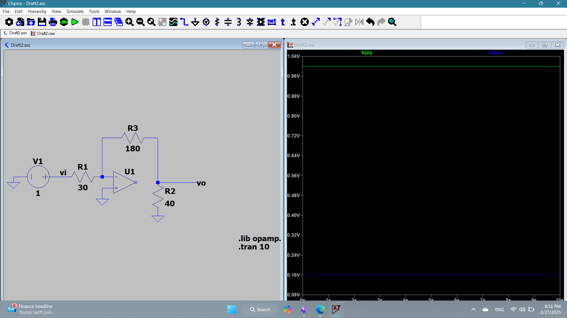
The circuit represents an inverted amplifier configuration with a gain of -6. The input voltage is 1V (green), and output voltage is -6v (blue). As noticed, the 40 k does not affect the gain.
1c
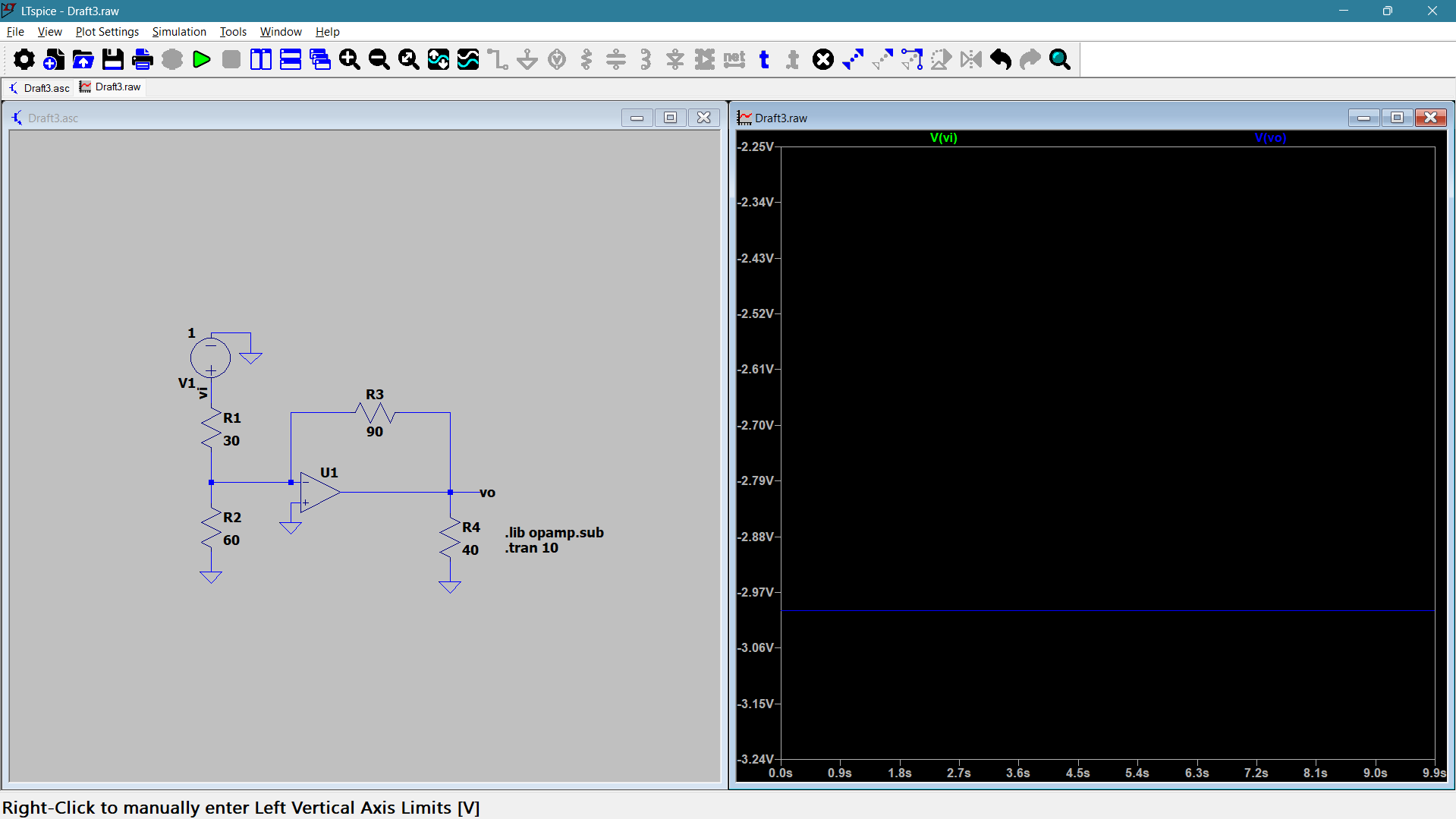
The circuit represents an inverted amplifier configuration with a gain of -3. The input voltage is 1V (green), and output voltage is -3v (blue). As noticed, the 40 k and the 60 k do not affect the gain.
1d
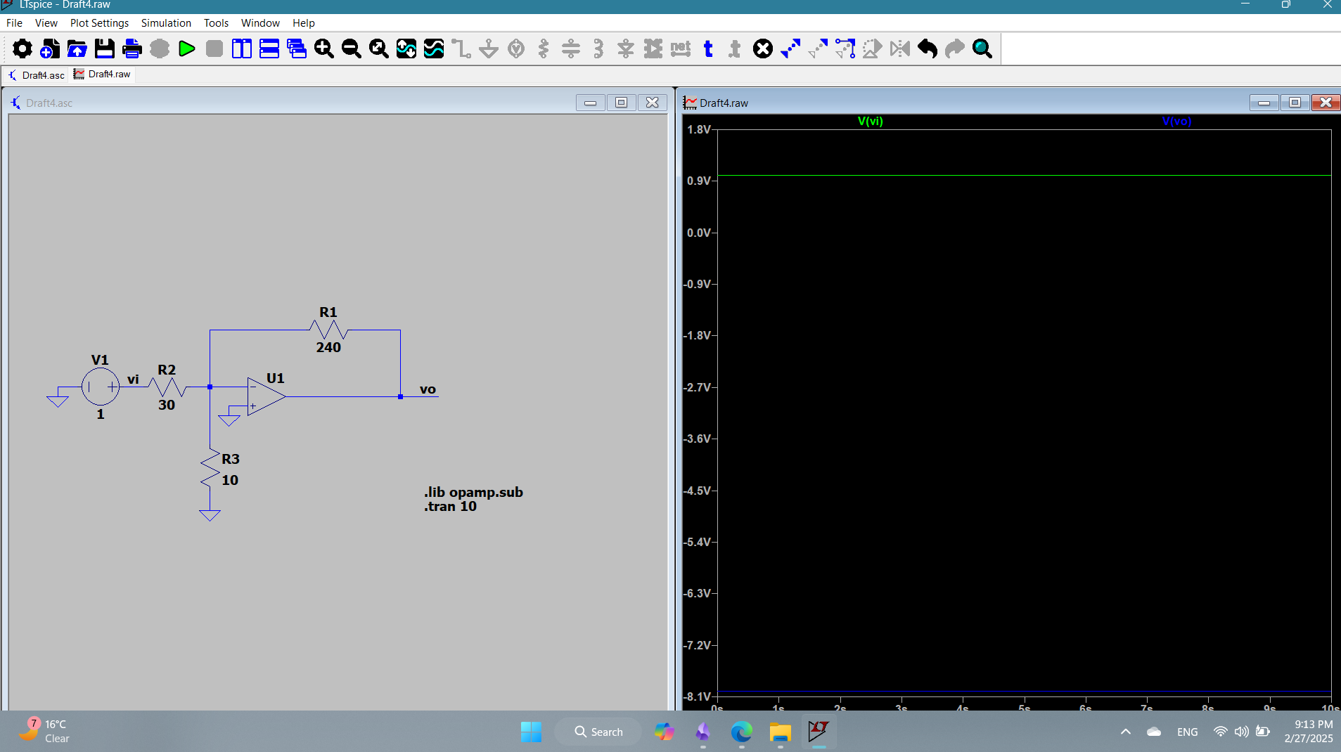
The circuit represents an inverted amplifier configuration with a gain of -8. The input voltage is 1V (green), and output voltage is -8v (blue). As noticed, the 10 k does not affect the gain.
1e
The circuit represents an inverted amplifier configuration with a gain of -6. The input voltage is 1V (green), and output voltage is -6v (blue). As noticed, both the 10 k and the 40k do not affect the gain.
1f
The circuit represents an inverted amplifier configuration with a gain of -4. The input voltage is 1V (green), and output voltage is -4v (blue). As noticed, the 60 k connected to the positive terminal does not affect the gain.
Problem 8
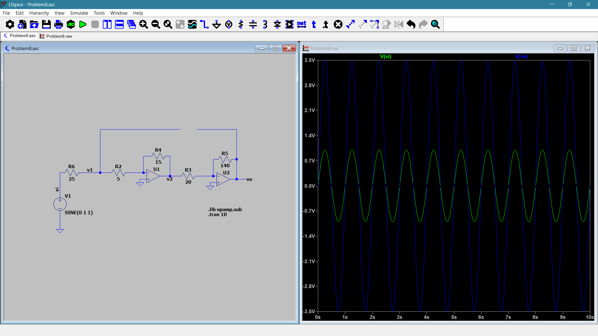
The input is a sine wave of amplitude 1V and the output is 3.5V in phase with the input due to double inversion.
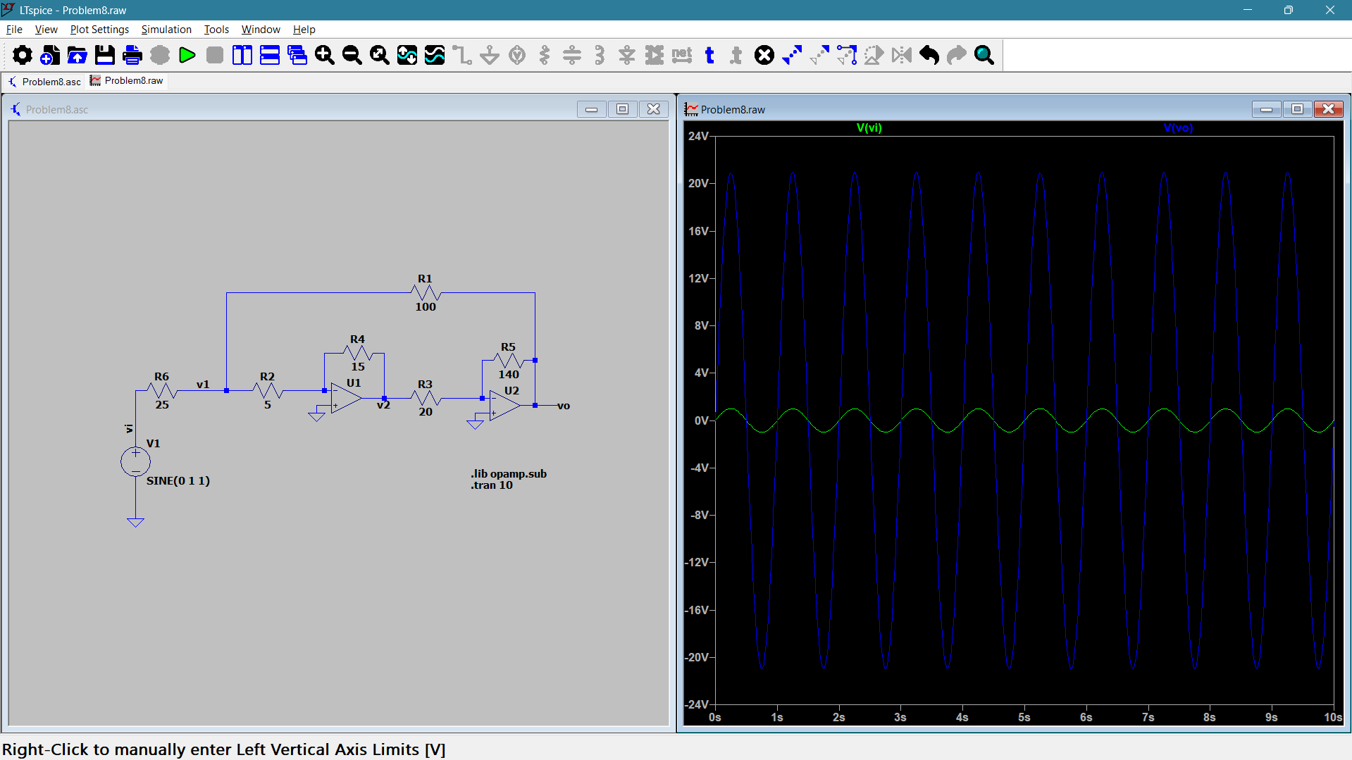
The input is a sine wave of 1V amplitude, and the output is 20V amplitude with no phase shift. This is because two inversions occurred, leading the output to be in-phase with the input.